

Spanning Tree Protocol Concepts and Configuration

When designing a switched network, one of the biggest issues that must be dealt with is loop prevention. If a loop were to develop in a switched network, the amount of traffic that could be passed between switches would quickly utilize the entire bandwidth available within each of the switches affected. One method to prevent loops is to only provide a single path between switches and ensure that there is no path redundancy across the entire switched network. While this may work in small deployments, when dealing with switched networks that are a bit larger the deployment of redundancy is a required element.
To be able to deal with these potential loops that could be caused by these redundant paths the Spanning Tree Protocol (STP) can be deployed. STP is tasked with preventing loops throughout the switched network. It does this by temporarily blocking redundant paths between switches; in this case, if the primary forwarding path is disrupted, this blocking would be removed allowing traffic to be passed. This article takes a look at some of the based STP concepts and reviews the configuration required to deploy STP on a switch.
Spanning Tree Protocol Concepts
The first thing to point out is that this article focuses on the original version of STP that is covered in IEEE 802.1D; some of the material about the newer Rapid STP (RSTP-IEEE 802.1w) will also be briefly discussed.
The basic function of STP is to provide a loop free switched network; this is done by creating a topology of all participating STP switches. The best loop free path through the switched network is then determined from this topology information. The initial step taken by each STP is to elect a root switch; the root switch is used as a central point in a switched network to determine the best route through the switched network. Initially, all switches act as if they are the root switch and do this until they receive traffic from another superior switch (as determined by switch priority); this is referred to as a root switch election.
Another thing that must be understood is that multiple root switches can exist in the network depending on what STP mode is being used. By default, on Cisco switching equipment, each VLAN has its own STP instance and a root switch is elected for each VLAN; this mode is called Per VLAN Spanning Tree Plus (PVST+). If implementing RSTP, Rapid PVST+ is used.
Spanning Tree Protocol Port Roles
Once the root switch is elected, each of the ports is given a role depending on its place within the STP topology; the available port roles when using 802.1D spanning tree are shown below:
- Root—The port given this role is the selected best path to reach the root switch
- Designated—The port given this role is selected with the best path to a specific switched segment; there is only one designated port per switched segment.
- Alternate—The port given this role is selected as a backup to the root port; if the root port should have a problem, this port would take over the root port role.
- Backup—The port given this role is selected as a back to the designated port; if the designated port should have a problem this port would take over the designated port role.
Once the best path is calculated and each of the ports has been given a role, all ports with the alternate or backup STP roles will be blocked to prevent loops.
Spanning Tree Protocol Interface States
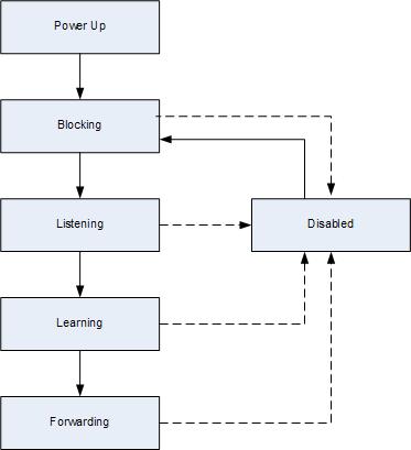
Each of the ports on a switch that are enabled participates in STP; each of these ports goes through a process of interface states before they are allowed to forward traffic. The sequence of 802.1D interface states is shown in Figure 1.
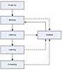 Figure 1 Spanning Tree States (802.1D)
As shown in Figure 1, there are five different states that a port can be in, described below:
- Blocking State—Ports that are in the blocking state do not forward traffic; they simply listen to the network to ensure that they should continue to block traffic. Should the state of the switched network change, the port could transition to listening state. All ports start in blocking state after initial switch initialization.
- Listening State—Ports that are in the listening state do not forward traffic. While in this state, the port will only listen to traffic as they did when in blocking state. This is the first state that comes after the blocking state after the port is set to start frame forwarding. The default time in the listening state is 15 seconds.
- Learning State—Ports that are in the learning state do not forward traffic; while in this state the port will listen to traffic and begin to learn addresses from the connected devices on a segment. The default time in the learning state is 15 seconds.
- Forwarding State—Ports that are in the forwarding state forward traffic as well as continue to learn addresses from the segment.
- Disabled State—Ports that are in the disabled state do not forward traffic or listen to the network traffic.
When implementing the RSTP, the time that a port takes to transition and the method used to transition has changed. This provides the ability for a switched network to begin forwarding traffic sooner without unneeded delays; these delays are a common complaint about the 802.1D version of STP.
Spanning Tree Protocol Configuration
By default, STP is enabled on VLAN 1 and all newly created VLAN’s; because of this there are no commands required to enabled STP on a newly initialized switch. If for some reason an older switch has STP disabled on a specific VLAN, the commands shown in Table 1 are used to re-enable STP.
Table 1: Enabling STP
| Step 1 | Enter privileged mode. | router>enable |
| Step 2 | Enter global configuration mode. | router#configure terminal |
| Step 3 | Enable STP on a VLAN. | router(config)#spanning-tree vlan vlan-id |
| Step 4 | Exit configuration mode. | router(config)#end |
When initially setting up STP, it is best to determine which of the switches on the network will become the root switch. While it is possible for the network to determine this by itself, the election will simply come down to a question of who has the lowest MAC address. By default, each switch begins with a priority of 32768; this priority is then combined with the MAC address of the switch to create the bridge ID. During a root switch election, the switch with the lowest bridge ID will be elected the root switch.
The commands to determine the root switch are shown in Table 2.
Table 2: Root Switch Selection
| Step 1 | Enter privileged mode. | router>enable |
| Step 2 | Enter global configuration mode. | router#configure terminal |
| Step 3 | Set the switch to become the root switch.This command determines the switch priority required to make the switch root and changes the switch priority to this number. | router(config)#spanning-tree vlan vlan-id root primary |
| Step 3 | Set the switch to become the secondary root switch.This command changes the priority of the switch to 28672. | router(config)#spanning-tree vlan vlan-id root secondary |
| Step 3 | Set the switch priority, as the default switch priority is 32768 any value less then this will make the switch root.It is recommended that this command not be used in favor of the earlier commands. | router(config)#spanning-tree vlan vlan-id priority priority |
| Step 4 | Exit configuration mode | router(config)#end |
If the default Spanning Tree mode needs to be changed from the default of PVST+, use the commands shown in Table 3.
Table 3: Spanning Tree Mode
| Step 1 | Enter privileged mode. | router>enable |
| Step 2 | Enter global configuration mode. | router#configure terminal |
| Step 3 | Configure the Spanning Tree mode to use. | router(config)#spanning-tree mode {pvst | rapid-pvst} |
| Step 4 | Exit configuration mode. | router(config)#end |
Summary
STP is one of those protocols that are used by most people without them even knowing that it exists, but without it modern switched networks could not operate. Hopefully the contents of this article have been able to introduce the concepts used by STP to eliminate switch loops and how STP can be configured to get the best performance out of the network.
Refernce


